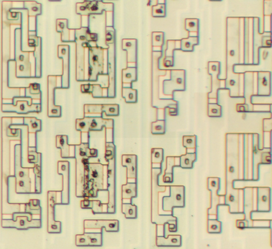
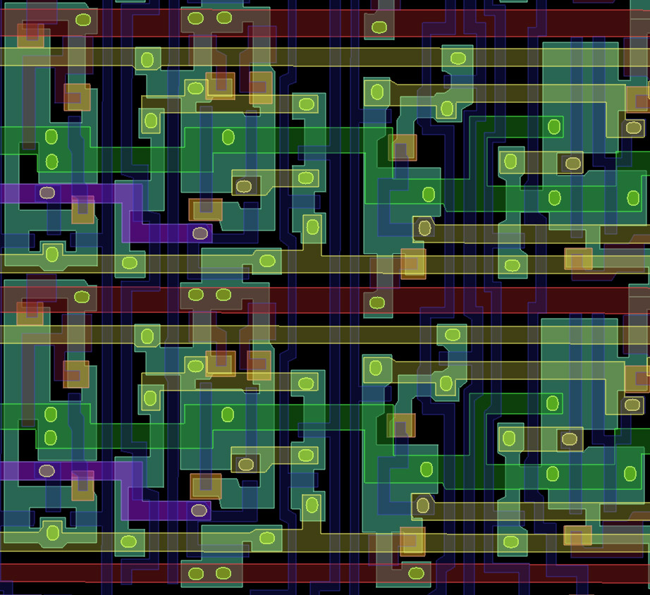
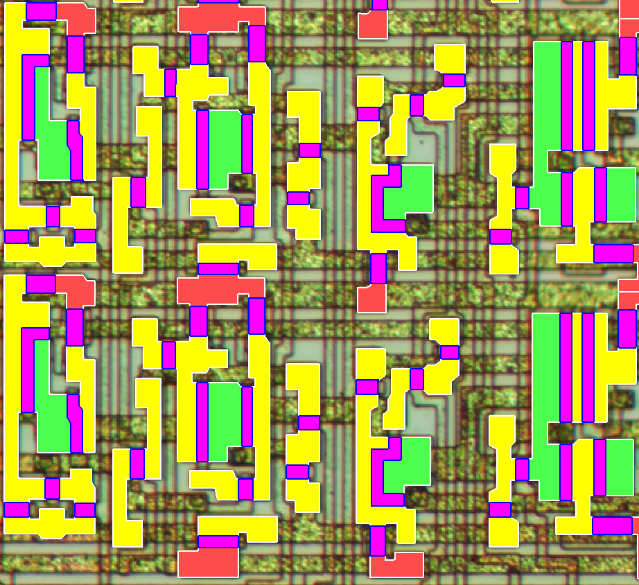
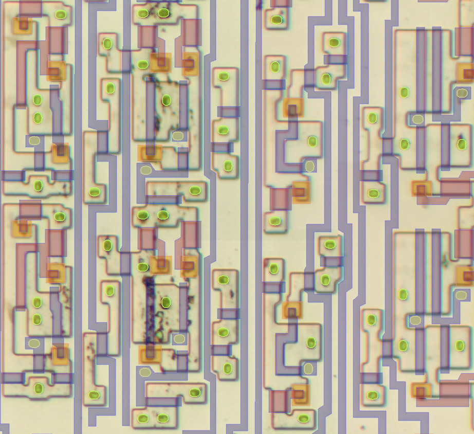
6502 Stack Register High Bits

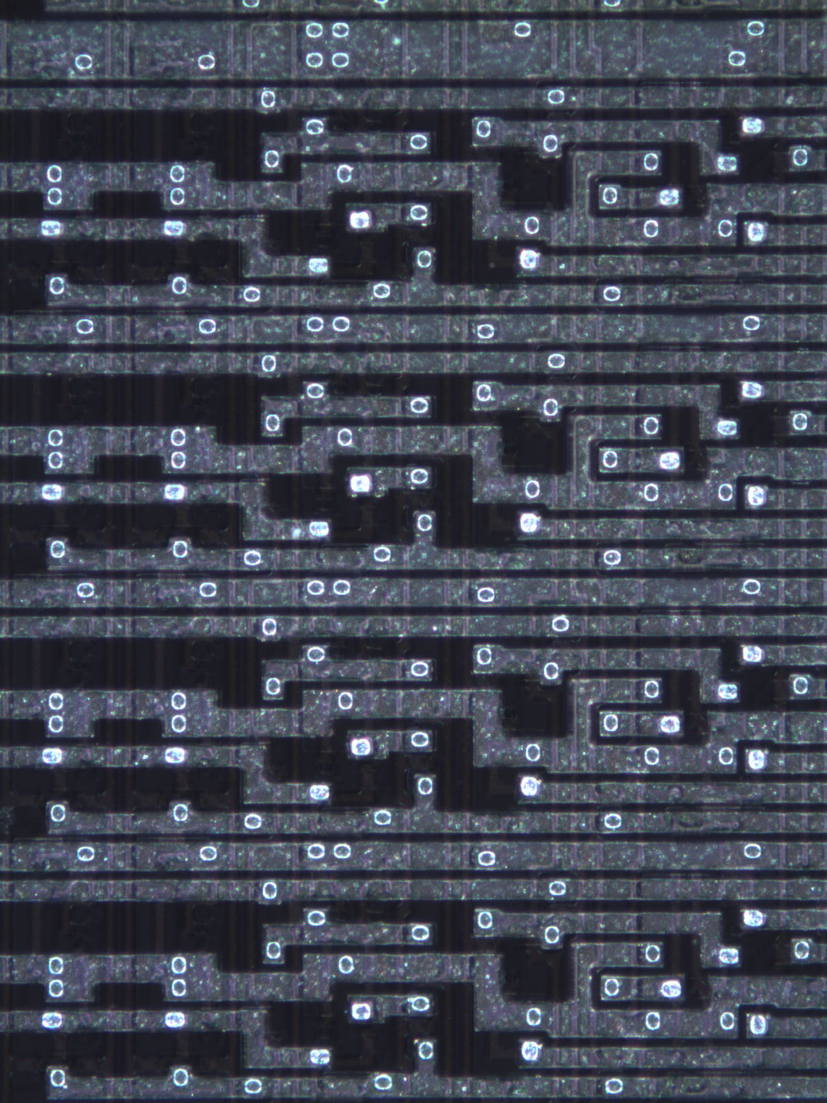
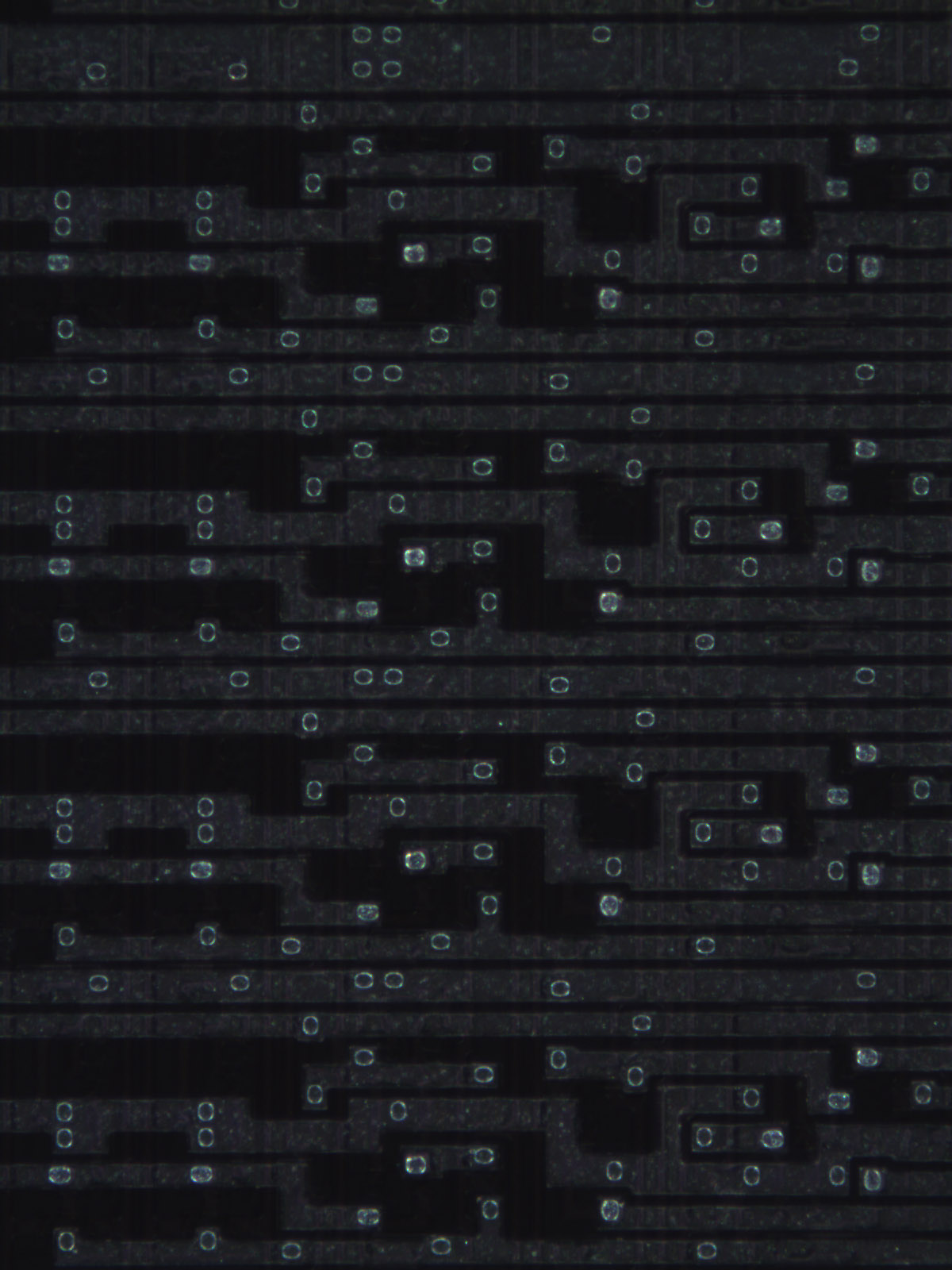
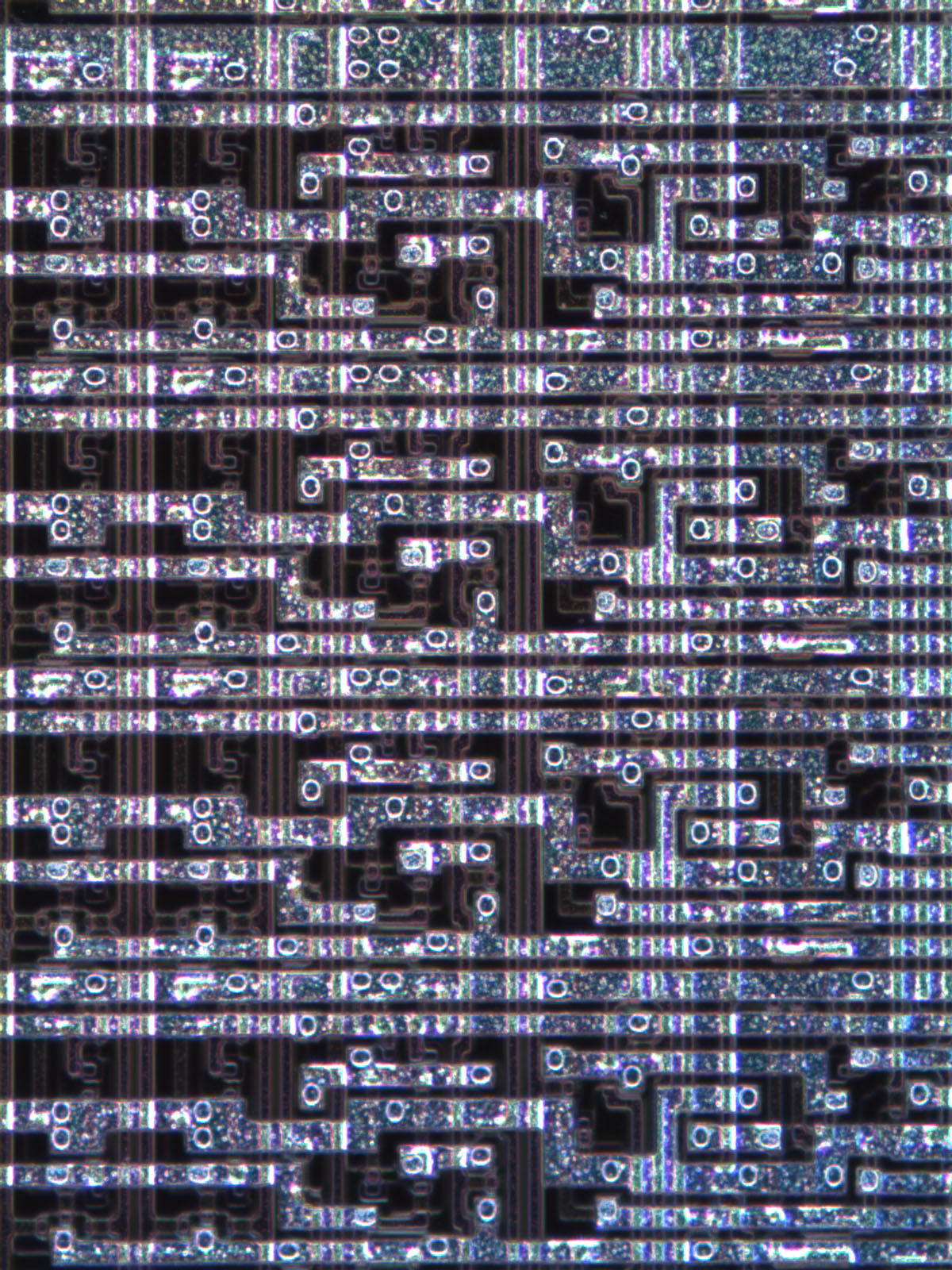
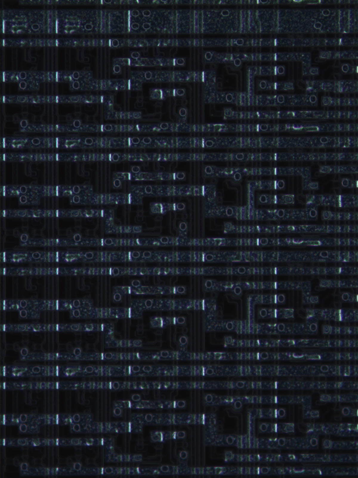
A series of aligned photographs of the chip surface, chip substrate, and polygon model.
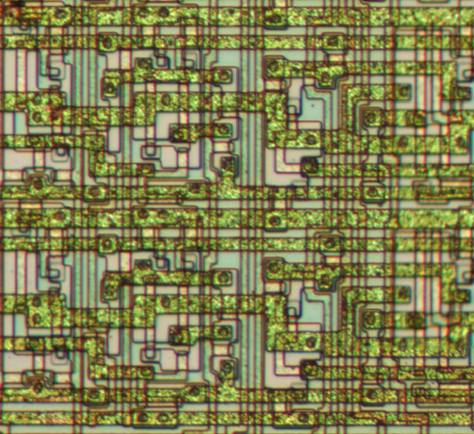
Chip surface
Chip surface
Chip substrate showing conductive substrate regions
Vector polygons representing chip features.  The purple trace carries one phase of the clock
Vector polygons representing chip features. The purple trace carries one phase of the clock
Conductive substrate tied to ground (green), +5V (red), or floating (yellow), with transistors (purple)
Vector polygons over the chip substrate image

= 6507D register section = A series of aligned photographs: brightfield, brightfield with crossed polarizers, darkfield
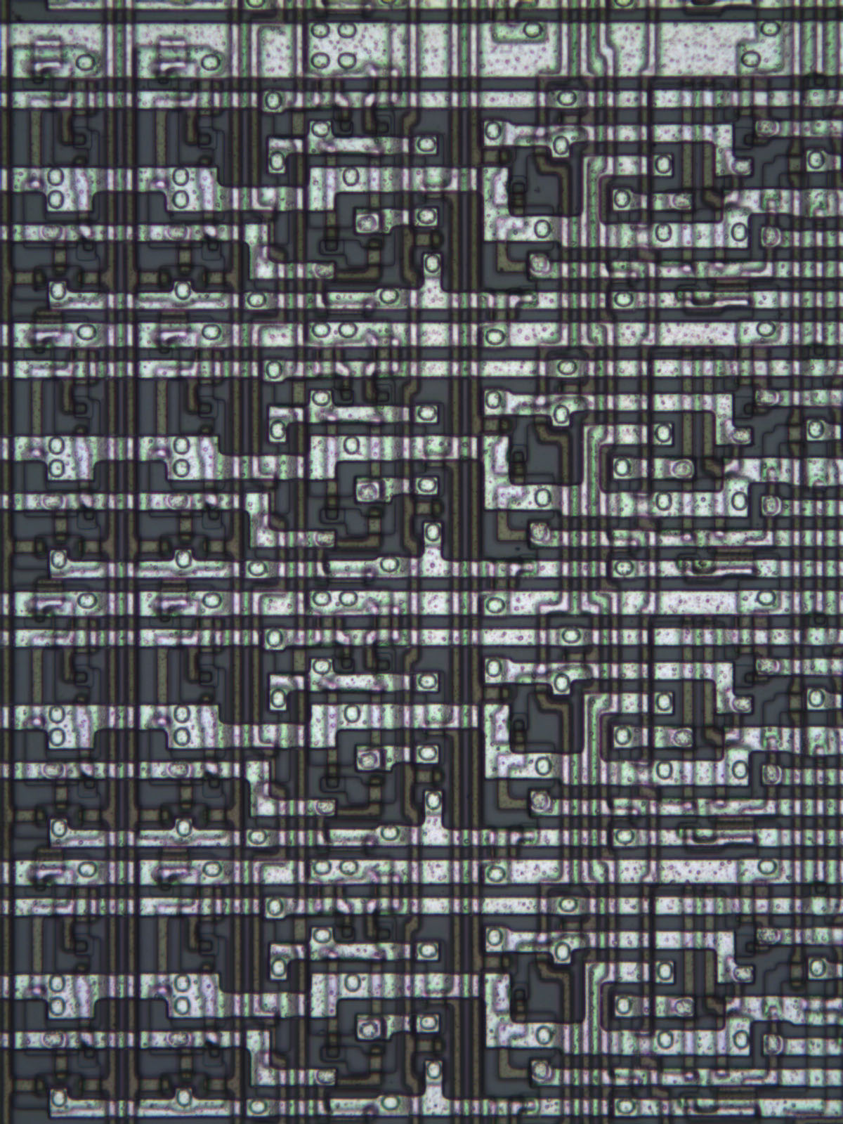
6507, 20x objective, brightfield
6507, 20x objective, brightfield, partly crossed pol
6507, 20x objective, brightfield, 90 deg pol
6507, 20x objective, darkfield